The basic information on how a transformer works was explained in the previous article. It is worth developing a few further concepts and relationships, however, in order to understand the functionality, operating principles and construction of this type of device even better.
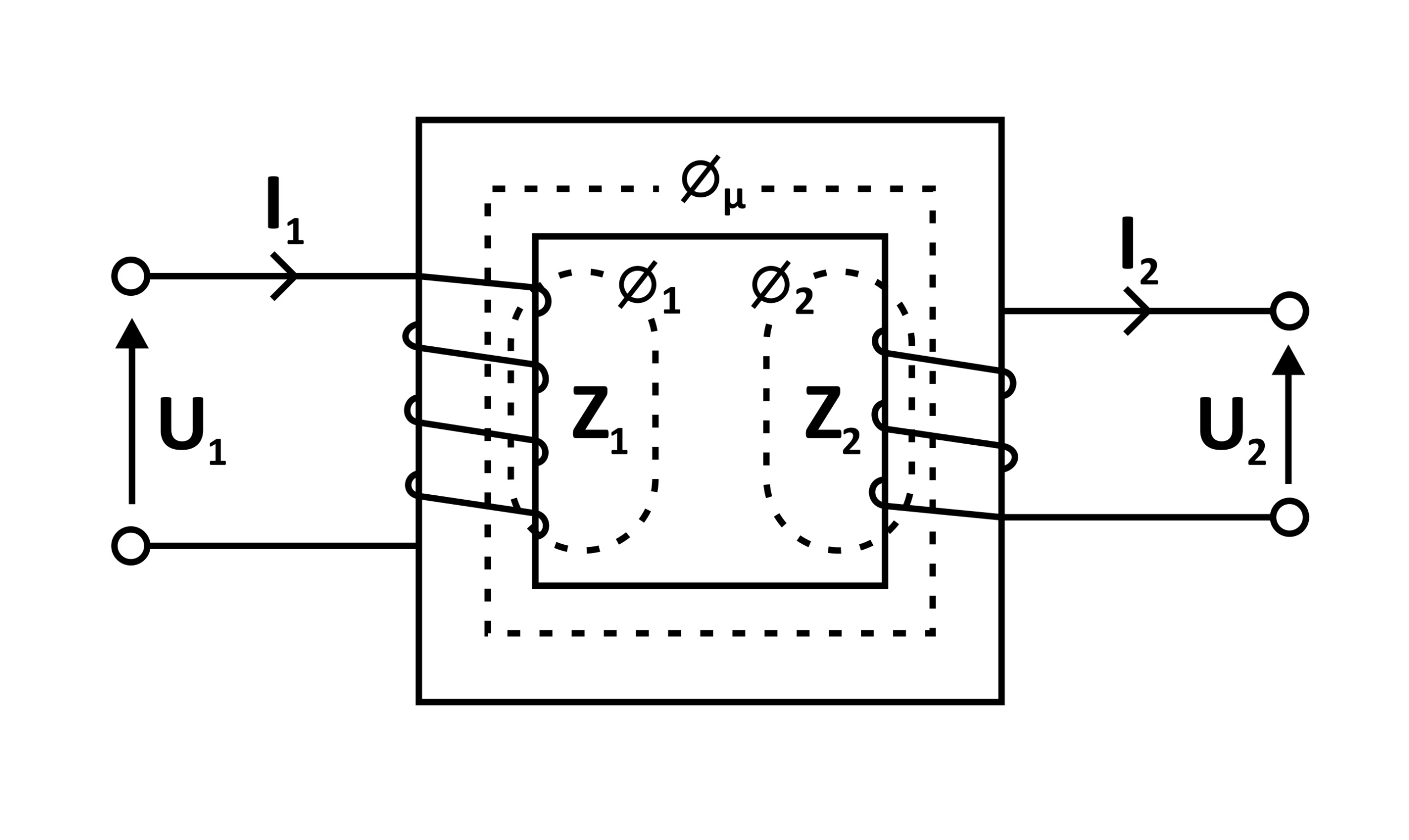
As we know, a transformer consists of a core on which the primary and secondary windings are wound.
 An alternating voltage U1 is applied to the terminals of the primary winding, and this causes a current flow of value I1 in the coil of the primary winding.
The alternating electric current I1 produces an alternating magnetic field whose lines of force close within the ferromagnetic core. For the magnetic field, this core is a far better path (that is, it has a higher magnetic permeability) than the air surrounding the coil. We say here that an alternating magnetic flux flows in the core.
The same flux passes through the interior of the secondary winding coil, inducing in it an electromotive force, which manifests itself as the appearance of an alternating voltage at the terminals of the secondary winding (the phenomenon of electromagnetic induction).
The same flux also passes through the primary winding coil, inducing in it an electromotive force directed against the supply voltage (Lenz’s law).
The alternating magnetic flux is common to both windings, and the induced electromotive force is the same for every single turn (Ampere’s circuital law), which is why the voltage that appears at the terminals of the secondary side depends mainly on the ratio between the number of turns in the primary winding coil and the number of turns in the secondary winding coil. In this simple way, by using different numbers of turns in the two windings, we obtain a change of voltage – that is, transformation.
Fig. 1
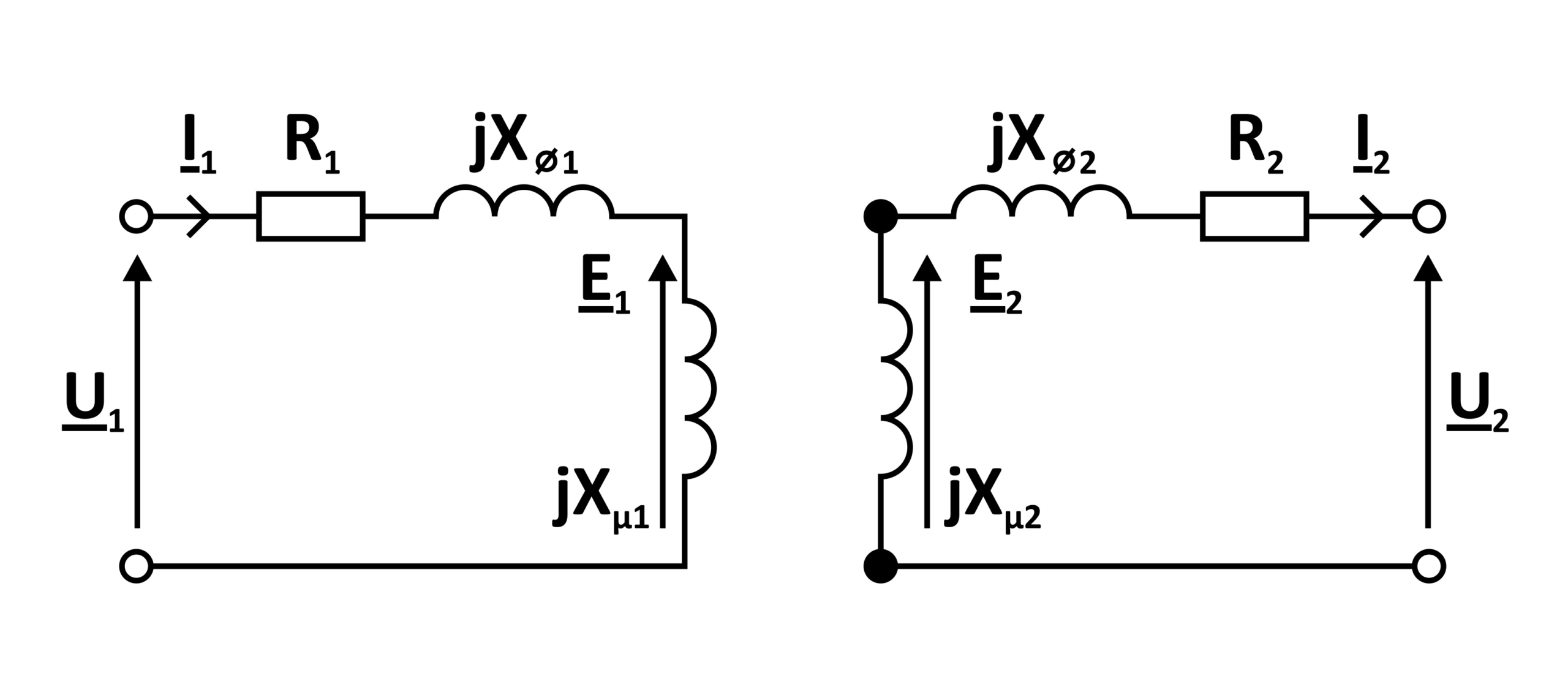
R1 and R2 – winding resistances
XΦ1 and XΦ2 – leakage reactances of the primary and secondary sides, representing those parts of the magnetic flux that close in the space not enclosing the other coil (closing mainly through the air)
E1 and E2 – induced electromotive forces
On the basis of the designations given above, the following basic concepts are introduced:
n = Z1 / Z2 – turns ratio
If the magnetising flux is common to both windings, it is clear that it will induce the same electromotive force in every turn. The same ratio can therefore be defined as the ratio of the electromotive forces
n = E1 / E2
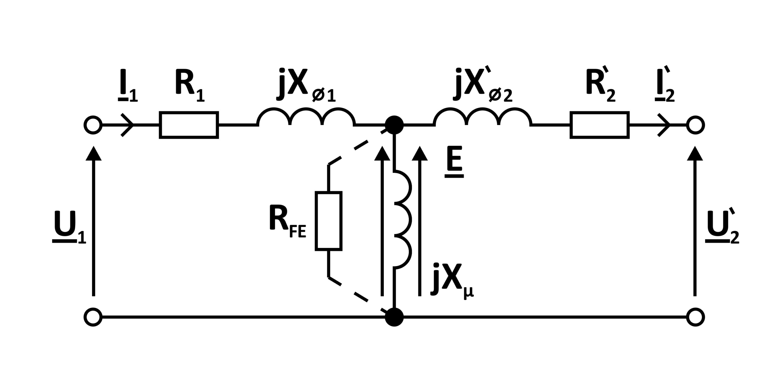
By applying the above formula for the ratio, we can refer the values of the secondary side elements from Fig. 2 to the primary side. Then:
U’2 = nU2 ; I’2 = I2/n ; R’2 = n2R2 ; X’Φ2 = n2 XΦ2
This gives rise to the commonly used equivalent circuit of the transformer.
Fig. 3: