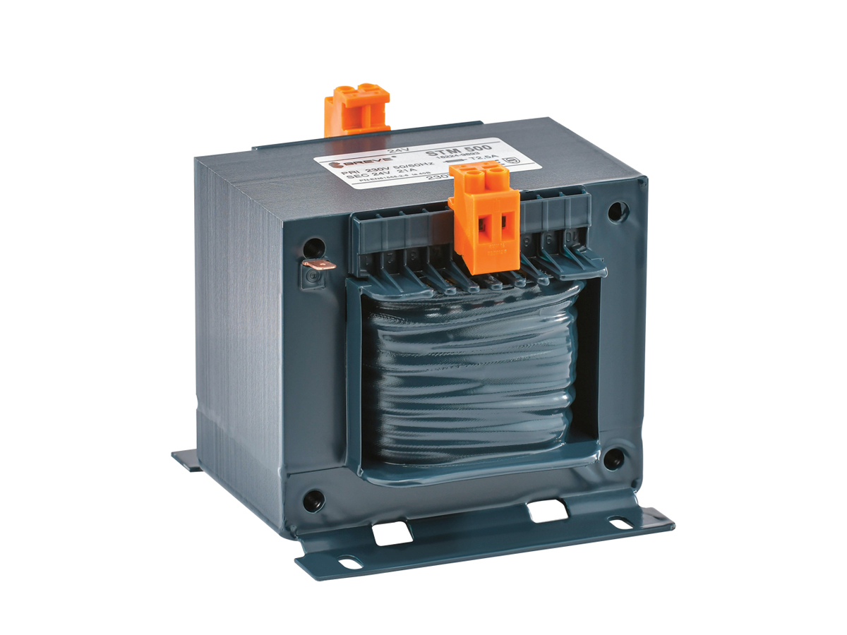
A transformer is used to convert an alternating voltage of a given value into an alternating voltage of a different value, while maintaining the same frequency. A special case is that of transformers which do not change the voltage values, but which then serve to provide galvanic isolation of the supplied equipment from the mains supply network.
There are a number of rules and laws in the field of electrical engineering that are applied in the design of transformers. One of the more advanced theories, from which one may start explaining the phenomena occurring in the voltage transformation process, is that of Maxwell’s equations. Their interpretation and simplification also give rise to other laws and rules that can be found in electrical engineering literature. These include:
- the Biot-Savart law used to determine the value of the magnetic flux density;
- Ampère’s circuital law defining the relationships between the magnitude of the current, the number of turns, the dimensions and the magnetomotive force;
- Faraday’s law / the law of electromagnetic induction defining the relationship between the induced electromotive force and the rate of change of the linked magnetic flux;
- Lenz’s law – determining the direction of the induced electromotive force as opposing the changes in the magnetic flux that gives rise to that force;
- the phenomenon of self-induction consisting in the induction of an electromotive force in a coil as a result of changes in the current flowing through that coil;
- the phenomenon of mutual induction consisting in the induction of an electromotive force in a coil as a result of changes in the current in another coil coupled with it.
The undesirable phenomena include:
- iron losses (the eddy current phenomenon);
- copper losses (power loss in the resistance of the winding wires);
- leakage flux (the closing of some of the magnetic field lines in a space not linked with the secondary winding);
- capacitive currents (resulting from the electrical capacitances between the windings and between the windings and the core);
- distortion of currents and voltages, and hence the appearance of higher-order harmonics as a result of the non-linearity of the magnetic circuit parameters.
Taking into account the most significant of the laws and phenomena listed above, a simplified model of a single-phase, two-winding transformer has been developed, on the basis of which its operating principle and the basic relationships between the input and the output quantities can be explained.