Three-phase transformers operate in the same way as single-phase transformers. The principle of operation is analogous. Here, however, we have a minimum of three supply conductors carrying alternating voltages phase-shifted by 120°. The windings of such a transformer are wound on three limbs of the core.
In typical cores, the winding wound on the centre limb produces a flux whose return path differs from that of the others, which must be taken into account during the design process.
The figure below shows, in simplified form, the construction of a three-phase transformer.
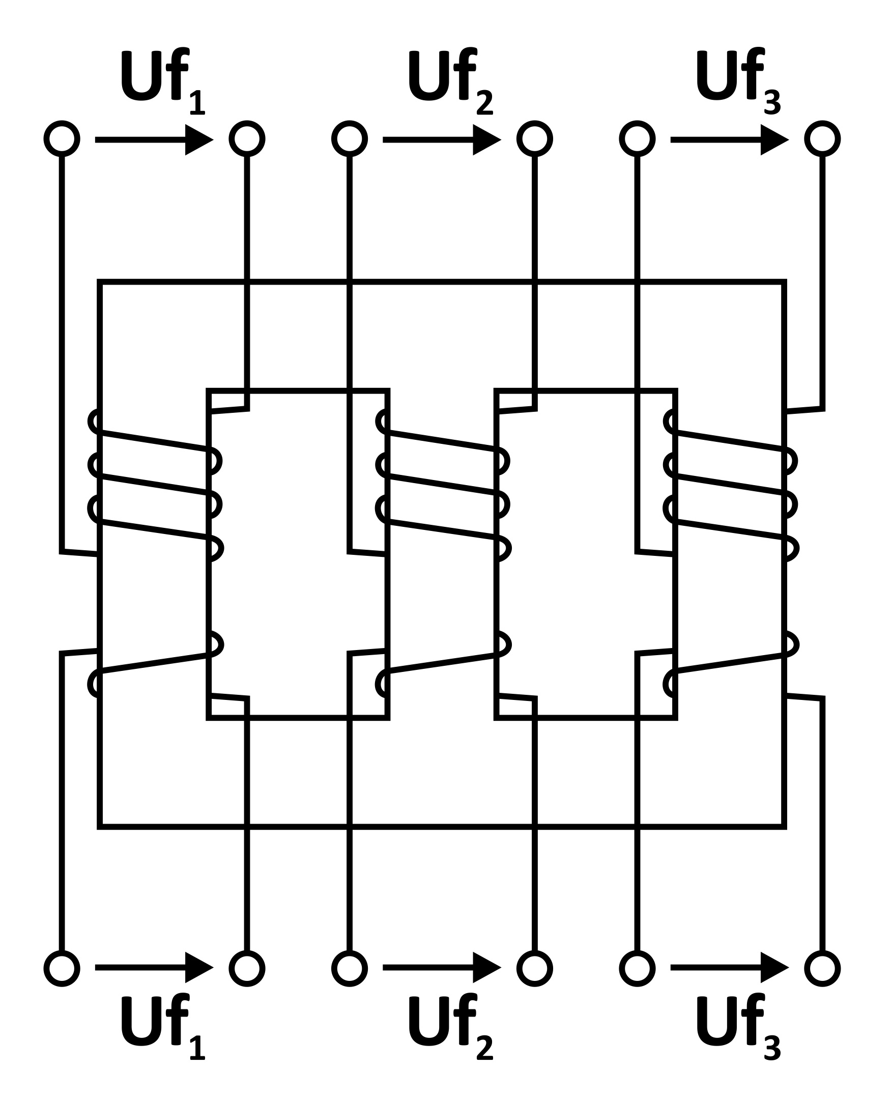
The voltages Uf1 … Uf3 are the phase voltages of the primary side, while uf1…uf2 are the phase voltages of the secondary side. In practice, three or four conductors are brought out from the primary and secondary sides (four conductors occur when the so-called neutral point is additionally brought out). It follows that the windings are interconnected before the terminals.
There are many methods of connection. The figure shows the three basic ones.
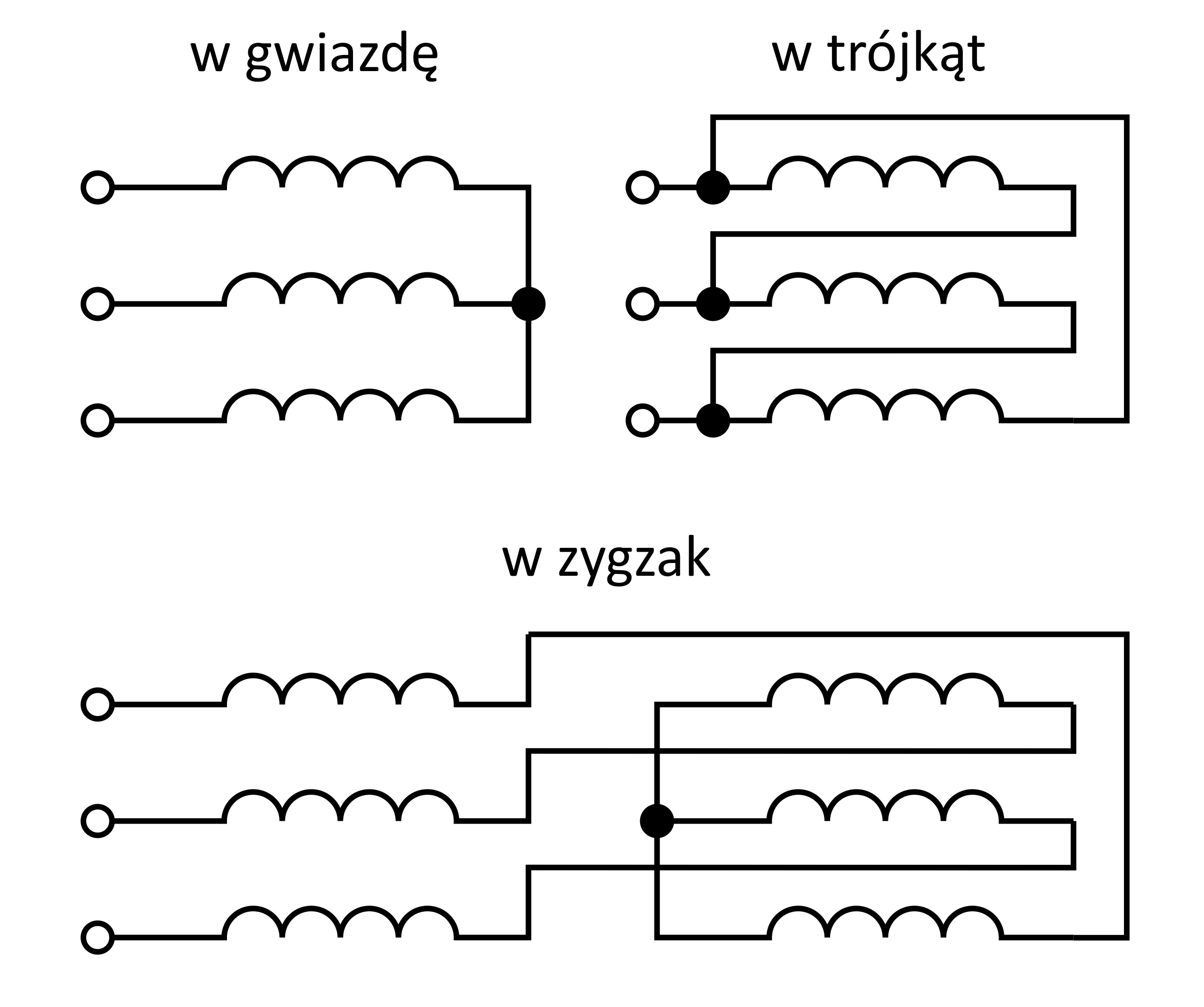
The zigzag connection requires the winding coils to be split into two parts.
By convention, the connection method is designated by means of letters:
|
Connection method
|
Primary windings
|
Secondary windings
|
|
Star
|
Y
|
y
|
|
Delta
|
D
|
d
|
|
Zigzag
|
Z
|
z
|
The windings on the primary and secondary sides may be connected in the same way, i.e. Yy, Dd, Zz, or in a mixed manner: Yd, Dy, Yz, Dz. This naturally affects the properties of the transformer. One of the reasons for creating such voltage combinations is to achieve appropriate magnetisation of the core for various applications, which is of considerable importance in the case of unbalanced loading of the secondary side. The connection methods also affect the voltage ratio and the angular displacement of the output voltage vectors relative to the input ones. Provided that the primary and secondary sides are connected in the same way, no phase displacements occur, and the turns ratio of the transformer is the same as the voltage ratio. Example:
Yy – n =N1 / N2 = U1R/ U2R
If, however, the connections are mixed, then the turns ratios and voltage ratios differ.
Dy – n =N1 / N2 = √3 U1R/ U2R
Yd – n =N1 / N2 = U1R/ √3U2R
Yz – n =N1 / N2 = √3 U1R/ 2U2R
In addition to the change in voltage ratio in mixed connections, a phase displacement occurs between the voltages supplying the primary side and the voltages of the secondary side. This is referred to as the so-called vector group (clock) number. If, for example, the secondary-side voltage is phase-shifted by an angle of 150◦, which corresponds to moving the hand of a clock from twelve o’clock to five o’clock, then we say that the clock number is 5.
A frequently encountered connection group is, for example, Dy11. This means that the primary-side windings are connected in delta, so the transformer can be supplied from a three-wire mains network, while the secondary side is connected in star, which makes it possible, in addition to bringing out three current terminals, to bring out a fourth terminal common to the windings, the so-called neutral point. The secondary-side voltages lag the primary-side voltages by an angle of 330°, or it may equally be said that they lead the primary-side voltages by an angle of -30°.

Krzysztof Majewski, MSc Eng
Sales Department Manager
Breve-Tufvassons