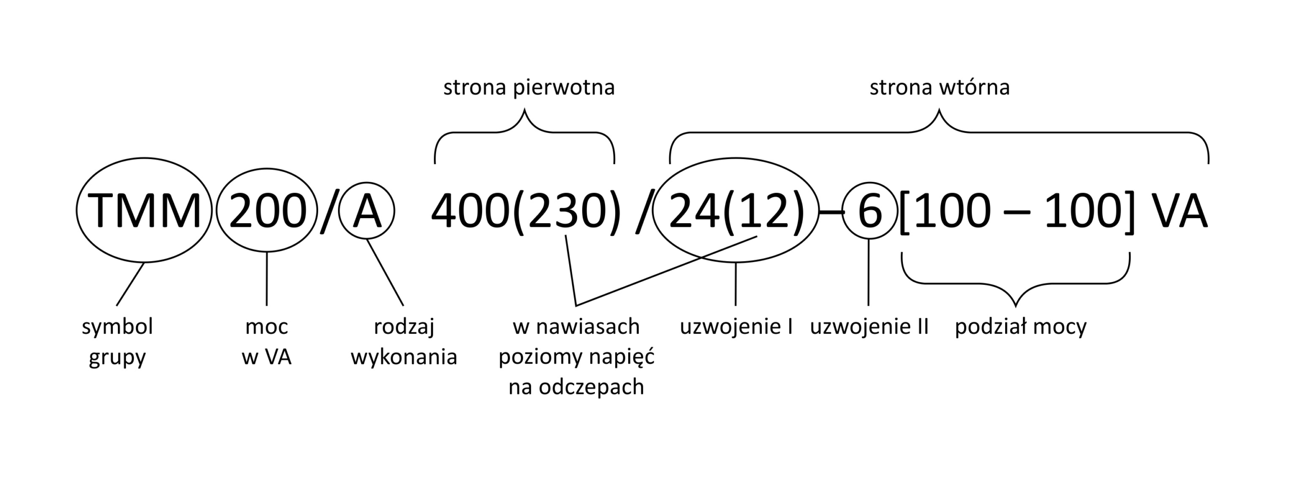
We often come across situations in which it becomes necessary to use a transformer with several secondary windings or windings with tappings. Transformers of this type, classified as so-called combined transformers, are usually made for the manufacture of various pieces of equipment.

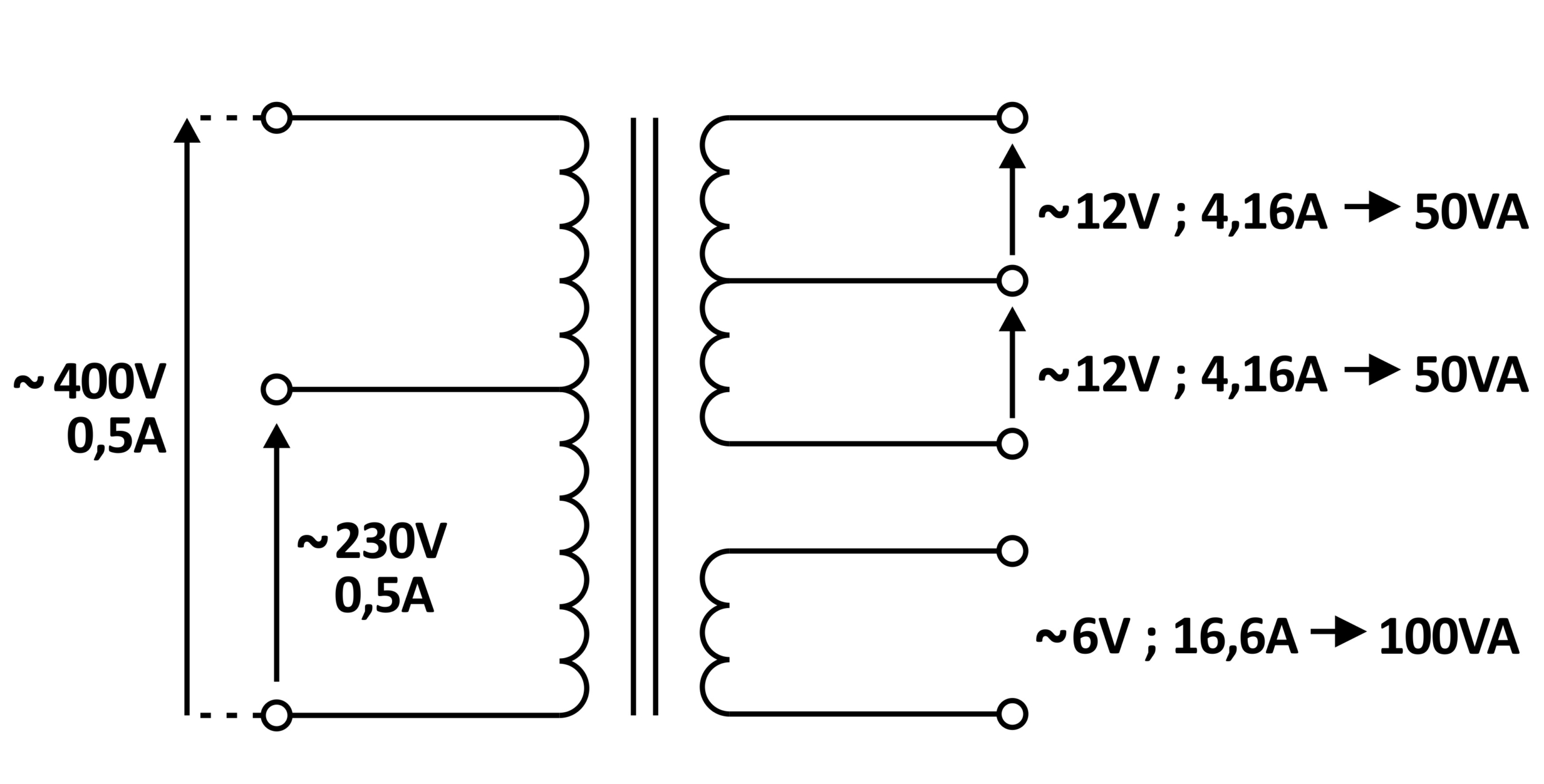
This transformer has one primary winding designed for a maximum supply voltage of 400V, with a tapping for an alternative supply of 230V.
It should be noted that, with primary windings fitted with tappings, only one of them may be energised at a time.
There are two windings on the secondary side. The first is designed for a voltage of 24V with a rating of 100VA, with a centre tapping dividing the 24V into 2x12V. With such a division, the maximum load power for each of the 12V voltages is 50VA. The second winding is designed for a voltage of 6V, for a maximum load power of 100VA.
It is important to note that, with the parameters given in this way, the ratings of the secondary windings apply only to the case in which the transformer is supplied with 400V, because the stated voltage multiplied by the stated current of 0.5A gives a power of 200VA, which corresponds to the sum of the ratings given for the secondary windings.
If, however, the transformer is supplied with 230V (to the tapping of the primary winding), the voltages on the secondary side will retain their values, but the total power drawn from the secondary side may not be greater than the product of 230V and the stated current of 0.5A, i.e. approximately 115VA.
It is of course possible to construct the transformer in such a way that, when supplied with 230V to the tapping of the primary winding, the full power of the secondary windings is still maintained.
In that case, the current stated at the tapping of the primary winding would be 0.87A. This would mean that the part of the primary winding running from the common terminal to the 230V tapping would be wound with winding wire of a larger cross-section. In such a situation, compared with the previous one, the transformer would in most cases have larger dimensions on account of the greater volume of the primary winding.
An example designation of the transformer shown in the figure would look as follows: